
A longer or higher-impedance route produces a bigger drop for the same current. The voltage drop check must be done together with current capacity and protection; passing one doesn't confirm the other.
Where do we measure the voltage drop?
The voltage at the load can be lower than the voltage at the start of the circuit, because conductors and connections have impedance. This difference is the route's voltage drop. A low incoming voltage at the building is a different problem; to tell them apart, the condition at the start and end of the route must be recorded under comparable load.
Measuring on a live circuit should be left to a trained person with suitable equipment. Signs such as dimmer light or difficulty starting a motor do not fix the cause; a fault in the device itself or in the supply can create a similar symptom.
The single-phase and three-phase formulas with clear units
For a balanced load and steady conditions, with R and X in ohms per kilometer, current I in amperes and the one-way route length L in kilometers, the following relations can be used:
Balanced 3-phase: ΔU = √3 × I × L × (R cosφ + X sinφ)
Voltage drop (%) = 100 × ΔU / U
In the percentage relation, U is the phase-to-neutral voltage for a single-phase phase-and-neutral circuit, and the line-to-line voltage for a balanced three-phase circuit. R must be consistent with the operating temperature and the conductor type. For a simple resistive load, the power factor is one and the reactance's share in this relation is zero.
In the single-phase formula, the factor 2 accounts for the outgoing and return path; don't double the length again. Also don't mix meters with kilometers. For an unbalanced network, harmonics or a special configuration, a suitable calculation method must be used.
Reference for this section: Schneider Electric: calculating voltage drop under steady load
A teaching example: the effect of route length
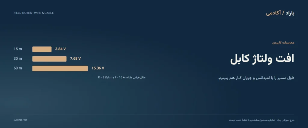
Assume a single-phase 230-volt circuit with a resistive load and a constant current of 16 amperes. The resistance of each conductor in this example is assumed to be 8 ohms per kilometer. This number is not attributed to a specific product or cross-section and is not an example of choosing a cable.
| One-way length | Calculated drop | Drop as a percentage of 230 V |
|---|---|---|
| 15 meters | 3.84 volts | About 1.67 percent |
| 30 meters | 7.68 volts | About 3.34 percent |
| 60 meters | 15.36 volts | About 6.68 percent |
For the 30-meter row we have: two times 16 times 0.03 times 8, equal to 7.68 volts. We kept the current and resistance constant so only the effect of length shows; in a real load, its behavior may change with the voltage.
Is the permitted limit always three or five percent?
No. Permitted limits depend on local regulations, the type of supply, the use and the circuit. For some installations supplied directly from the public low-voltage network, Schneider's guide shows sample values of 3 percent for lighting and 5 percent for other uses; the same page gives other values for another kind of supply.
Don't take these numbers as a firm rule for all projects in Iran or as permission to choose a cable. The design limit and the project's current requirements must be determined. A drop when starting a motor is also not the same as controlling the drop in steady operation, and upstream drop must be included when assessing the whole route.
Reference for this section: Schneider Electric: voltage drop limits and the conditions they apply under
What helps reduce the drop?
- Shorten unnecessary length and remove a faulty connection after a technical review.
- Choose a cross-section and conductor material with a suitable impedance for the route.
- Review the supply route and the load distribution in the design.
- Check the voltage at the start and end of the circuit, both in normal operation and in sensitive conditions.
Increasing the cross-section does not fix every cause of low voltage. For a pump or an air conditioner, that device's documents and its starting method must also be checked. explains an example of this difference.
A second example: a three-phase circuit
Consider a 380-volt three-phase circuit, a resistive load, a current of 20 amperes, a one-way length of 50 meters and a 6 mm² copper conductor. For this example, we take the resistivity of copper as about 0.0175 ohm·mm²/m and ignore the effect of reactance.
Resistance per meter: 0.0175 ÷ 6 ≈ 0.00292 ohm.
Voltage drop: 1.732 × 20 × 50 × 0.00292 ≈ 5.05 volts.
Percentage drop: 5.05 ÷ 380 ≈ 1.33 percent.
A conductor's resistance at its operating temperature is higher than the 20-degree value; so in a real calculation, read the resistance for that model and operating temperature from the datasheet.
A third example: a 24 V load such as a camera
A 2-ampere load on a 24-volt DC supply, a one-way length of 40 meters and a 1 mm² copper conductor. In a single-path circuit, the out-and-back route is 80 meters.
Route resistance: 0.0175 × 80 ÷ 1 = 1.4 ohm.
Voltage drop: 1.4 × 2 = 2.8 volts; that is about 11.7 percent of 24 volts.
With 2.5 mm²: 0.56 ohm, a drop of 1.12 volts and about 4.7 percent.
A one-volt drop is small in a 230-volt circuit, but becomes a large percentage in a 24-volt circuit. For cameras, LED lighting and low-voltage equipment, always calculate the route drop and look at the manufacturer's recommendation for the minimum input voltage.
Frequently asked questions
Does voltage drop depend only on length?
No; current, conductor impedance, temperature, power factor and the connections along the route also have an effect.
Can one fixed factor be used for all cables?
The factor must match the construction, temperature and circuit conditions. Don't use another model's factor without matching it.
The cable is suitable for the current; is the voltage drop acceptable too?
These are two separate checks. A long route may be thermally suitable and unsuitable for voltage drop.
Products related to this topic
These products are presented for studying construction and specifications; they are not a size selection or an approval for use in a specific circuit.
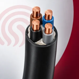
Underground cable 4x6 Khorasan Electric (Afsharnejad)
A 6 mm² cross-section; useful for this article's three-phase examples.
1,355,000 toman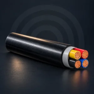
Underground cable 4x16 Khorasan Electric (Afsharnejad)
A larger cross-section for comparing the effect of cross-section on route drop.
3,430,000 toman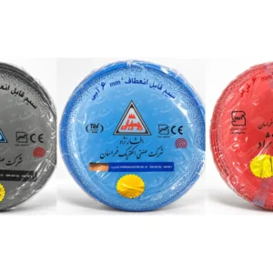
Flexible wire 6 Khorasan Electric (Afsharnejad)
A single-core wire sample with the same cross-section for comparing models.
271,000 toman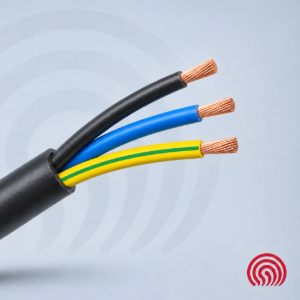
Flexible cable 3x4 Khorasan Electric (Afsharnejad)
A sample from the same field for comparing construction, size and specifications.
660,000 toman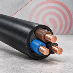
Underground cable 3x2.5 Khorasan Electric (Afsharnejad)
A sample from the same field for comparing construction, size and specifications.
490,000 toman