

For one size there is no single permanent current rating. A table's number only makes sense under that table's reference conditions and, after applying the relevant factors, must be coordinated with the load and the protection.
What is the difference between load current current capacity and breaker current?
Load current is what the circuit needs to supply the load. A cable's current capacity is its thermal capacity under defined installation conditions. The rated current or setting of the protective device is the third parameter; treating these three numbers as equal without checking the design is not correct.
For ordinary circuits with overload protection, the overall coordination is expressed by the relation below; but this relation is only the selection part, and short-circuit checking, voltage drop and the circuit's special requirements remain.
Here IB is the design load current, In is the rated current or setting of the protection, and Iz is the cable's current capacity under the installation conditions. The operating characteristic of the protective device must also be checked; simply making the breaker's amperage equal to a number in a table is not enough.
Reference for this section: Schneider Electric: coordinating the cable and the protective device
Why does the installation method change the result?
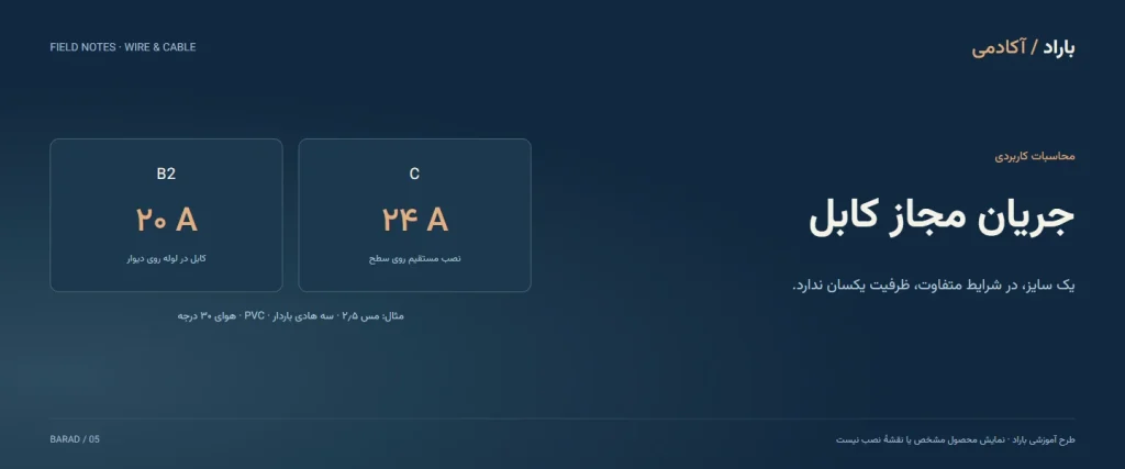
A cable on a surface, inside conduit, in thermal insulation or in the ground doesn't dissipate heat in the same way. The number of loaded conductors, the conductor material and the insulation type are also part of a table's definition. For example, a three-loaded-conductor table must not be extended without explanation to a circuit with two loaded conductors.
In soil, temperature, thermal resistance and the state of the route also come up. "Ambient temperature" means the air temperature at the installation site or the soil temperature concerned, not the temperature of a room away from the cable. Record the actual route conditions before choosing a table column.
A sample table: the difference between two installation methods
The table below is an educational excerpt from figure G20 of Schneider's guide: copper conductor, PVC insulation with a 70-degree conductor temperature, three loaded conductors and a reference air temperature of 30 degrees Celsius. B2 and C are names of reference methods; the environment and grouping factors have not been applied in these numbers.
| Cross-section of each conductor | Method B2: multicore cable in conduit on a wall | Method C: direct installation on a surface |
|---|---|---|
| 1.5 mm² | 15 A | 17.5 A |
| 2.5 mm² | 20 A | 24 A |
| 4 mm² | 27 A | 32 A |
| 6 mm² | 34 A | 41 A |
Reference for this section: Schneider Electric: installation method, current capacity and correction factors
How do we read the correction factors?
Every table has specific scope and assumptions. Temperature factors, grouping factors and other relevant conditions must be taken from that same reference method; don't combine factors that belong to incompatible cases. The simplified expression below only shows the logic of the calculation:
For a purely computational example, if the reference number is 32 amperes and the two applicable factors are 0.8 and 0.9 respectively, the result is 23.04 amperes. These factors are hypothetical and are not an instruction for choosing a real circuit. The result shows why the raw number from a table should not be taken directly as the basis for an order.
The order for checking a circuit
- Specify the design current and the load's starting conditions.
- Record the cable type, the installation method and the number of loaded conductors.
- Take the reference number and the applicable factors from compatible documents.
- Match the corrected capacity to the protection and the short-circuit conditions.
- Check voltage drop, connection limits and mechanical requirements separately.
Weight, apparent diameter or being flexible does not alone determine current capacity. In a technical inquiry, write the route conditions beside the load specifications so the question "how many amperes does it carry?" becomes a traceable review.
Reference for this section: Schneider Electric: methodology for choosing the cross-section
A step-by-step example: a single-phase circuit
This example only shows how to read it; the table numbers and factors are hypothetical and don't replace the model's documents and the project's standard.
Load current (Ib): 18 amperes. Protective device (In): 20 amperes.
Reference table number for the project's installation method: 27 amperes (hypothetical).
Ambient temperature factor: 0.94 and grouping factor: 0.8 (both hypothetical).
Corrected capacity (Iz): 27 × 0.94 × 0.8 ≈ 20.3 amperes.
The usual logic of the check is that the load current does not exceed the protective device's current, and the protective device's current does not rise above the cable's corrected capacity: 18 ≤ 20 ≤ 20.3. In this example the condition holds, but the margin is small, and voltage drop or a terminal may call for a larger cross-section.
Common mistakes when using the table
- Reading the wrong installation method column; for example, the cable-in-air column for a cable inside conduit.
- Ignoring the grouping of several cables in one route or duct.
- Using the copper table for an aluminum conductor.
- Treating current capacity as enough without checking voltage drop and terminal limits.
- Taking the number for one model and applying it to another model.
A table is a starting point. The final decision must be confirmed with that model's specifications, the project's conditions and the technical lead's opinion.
Frequently asked questions
Does a 2.5 cable always have a fixed amperage?
No. The two columns of the sample table also show that the installation method can change the number; other conditions must be applied as well.
Should we use the copper table for an aluminum cable?
No. The conductor material is part of a table's definition, and the column and documents suited to aluminum must be chosen.
Is a thicker cable enough to stop a breaker tripping?
First the cause of the tripping and the state of the load and circuit must be established. Changing the cable or the protection without this check may hide the problem.
Products related to this topic
These products are presented for studying construction and specifications; they are not a size selection or an approval for use in a specific circuit.
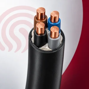
Underground cable 4x6 Khorasan Electric (Afsharnejad)
A sample for practicing reading the table and installation method with a specific cross-section.
1,355,000 toman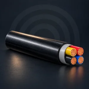
Underground cable 4x16 Khorasan Electric (Afsharnejad)
A larger sample for comparing capacity in the reference table.
3,430,000 toman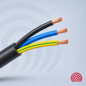
Flexible cable 3x4 Khorasan Electric (Afsharnejad)
A sample from the same field for comparing construction, size and specifications.
660,000 toman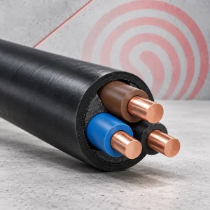
Underground cable 3x2.5 Khorasan Electric (Afsharnejad)
A sample from the same field for comparing construction, size and specifications.
490,000 toman